
LabVIEW Tutorial
Last updated on 19th Sep 2020, Blog, Embedded System, Tutorials
Before starting this lesson, you need to have LabVIEW installed and ready to run. You can check to see if it is installed by going to Start»All Programs»National Instruments»LabVIEW 2010. This course assumes that you have never written a computer program, but you’ll start programming right away! Have fun!
We are going to start learning how to program in LabVIEW by writing a program that will calculate the hypotenuse of a right triangle. You probably remember that the Pythagorean Theorem uses three sides of a right triangle, a, b, and c, where c is the hypotenuse.
Below is an example which is actually what we will be developing in LabVIEW. The sides a, and b are called legs of the triangle and c is the hypotenuse.
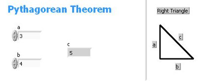
We can compute the length of the hypotenuse using the Pythagorean Theorem which is

which means that

We have to start by creating what the user will use to enter the values of a and b and the program will display the value of c. This is done in the front panel of LabVIEW. It is named front panel because a system such as a power generator has a front panel to display the status of the system. Make sure that LabVIEW is started and so that you see the Getting Started window.
You want to click File»New VI to create a new VI program. After you do that two windows appear, one is called the “front panel” and the other is called the “block diagram”. It is best to tile these windows so they are both visible on the screen, and you can do that by pressing CTRL-T. The following steps tell you how to create the user interface on the front panel
- 1.Move your cursor over to the front panel. This screen is blank right now and you are going to add controls and indicators to it in the next step.
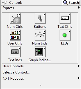
- 2.Controls are input values to the program and indicators are output from the program. We have two controls that the user can enter, these are “a” and “b”, and we have one indicator, “c”. Right click on the front panel screen and a control window similar to what is below will come up.Move your cursor over to the front panel. This screen is blank right now and you are going to add controls and indicators to it in the next step.
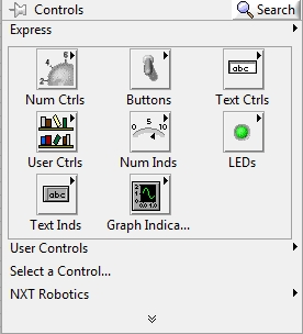
- 3.Controls are input values to the program and indicators are output from the program. We have two controls that the user can enter, these are “a” and “b”, and we have one indicator, “c”. Right click on the front panel screen and a control window similar to the window below will come up.
- 4.In the Express section of this window there are two buttons that we will expand: The “Num Ctrls” contains all of the numeric controls available to you and “Num Inds” contains all of the numeric indicators. Click on Num Ctrls and then drag the icon that says “Num Ctrl” to the front panel. This will have the value of the “a” side and you can rename this control by double clicking the text above the control and typing an “a”, the click anywhere on the front panel. This is how you can change the label above any front panel item. Do the same thing for the “b” side.
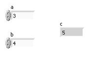
- 5.To create the indicator for the value of “c” select “Num Inds” in the Express window and then drag a numeric indicator, labeled “Num Ind” to your front panel. You can now arrange these controls and indicators like the Front Panel below.
- 6.Now we need to add the code to make the program take the values of “a” and “b” and compute “c”. If we run the program like it is right now it will only print a value of zero for “c” because it isn’t computing anything! Here are the steps to compute “c”.
- 7.Move your cursor to the block diagram. This will be a window containing only the two controls for “a” and “b”, and the one indicator for “c”. When you add a control or an indicator to the front panel it also adds it to the block diagram. We will add the code to this now. The image below shows the actual block diagram that you are going to create.
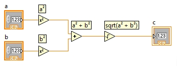
- 8.Right click on the block diagram and a functions window will come up. We want to square the value of “a” and “b” and to do that you want to click on the small arrow at the bottom of the functions window. Then click on the Mathematics Numeric icon and then drag the “Square” icon to the block diagram.
- 9.To square the value of a, we have to connect the control containing the ‘a’ value to the “square” function. When you move the cursor to the right of the control a roll of wire will appear and you want to hold the mouse and drag it to the left of the square function.
- 10.To square the value of b, you want to do steps 2 and 3 with the value of b. After you do that you will have the a2 and b2 and the next thing to do is to add these two values together.
- 11.You want to add an “add” function to the block diagram and you can do this by right clicking on it, selecting Mathematics, clicking on numeric, and then dragging the “add” icon to the block diagram.
- 12.The add function has two inputs and one output. The inputs are always on the left and the outputs on the right. So take the output of where you squared “a” and connect it to the top input of the add function and then take the output of squaring “b” and connect it to the bottom input of the add function. You now have a2 + b2.
- 13.The next step is to take the square root of a2 and b2 and you can do this by right clicking on the block diagram, select mathematics, select numeric, and then drag the square root icon to the block diagram. There is a single output from the add function and you want to drag that to the input of the square root function.
- 14.The last step is to drag the output of the square root function to the indicator having the “c” value. This will take the value of sqrt(a2 + b2) and display it on the screen.
- 15.To run your program click on the run arrow at the top of the screen.
Subscribe For Free Demo
Error: Contact form not found.
Your First LabVIEW Program
A program written in LabVIEW uses a slightly different approach than programs written in other languages. This is called dataflow programming and, when a function such as addition or subtraction executes it receives all required inputs before it can be executed. A function will produce output data and pass the data to the next node in the dataflow path. The movement of data through the nodes determines the execution order of the VIs and functions on the block diagram.
You may have done computer programming in languages such as Visual Basic, C++, or JAVA which follow a control flow model of program execution. In control flow, the sequential order of program elements determines the execution order of a program.
In LabVIEW, the flow of data rather than the sequential order of commands determines the execution order of block diagram elements. Therefore, you can create block diagrams that have simultaneous operations.
Take a look at the LabVIEW code to calculate the equation below.

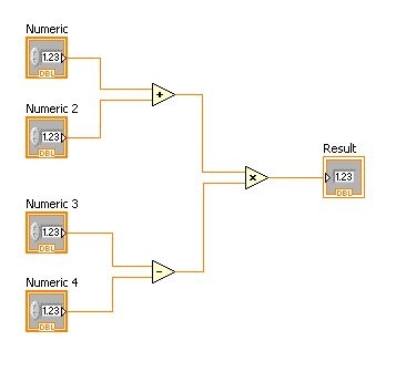
Notice in the equation we have parenthesis around the addition operation and subtraction operation. Without those, Numeric2 would be multiplied by Numeric3 and then the addition would be performed and finally the subtraction and this is not what we want. In LabVIEW there are no parentheses because we specify the order of execution by the placement of the function. In other programming languages, such as C++ or JAVA, each statement is executed sequentially meaning that one statement executes, then the next, and so on. In our LabVIEW program the addition operation and the subtraction operation can execute at the same time since one does not depend on the other.
Now you have a few options on where to go next. The next lesson will show you how to build the user interface which goes in the LabVIEW front panel. If you already know how to create the user interface you can do that on your own and move to the lesson on creating the code which goes in the block diagram.
The program you saw on the previous page is actually going to be used in this lesson to learn how to use LabVIEW, for the next lesson on tracing a program as it executes, and for a third lesson on debugging a program when you have errors.
It is probably very useful to go through some detailed tutorial instructions that tell you how to create a LabVIEW program and we will do that at this time. Make sure that you have a LabVIEW up and running.
- 1.Every LabVIEW program has a user interface where the user can enter data for the program to process and output that the program has generated and it has a set of code that indicates that processing is to take place. The user interface is called the front panel and the code is called the block diagram. To have both of these on the screen at the same time press ctrl-t to tile the windows.
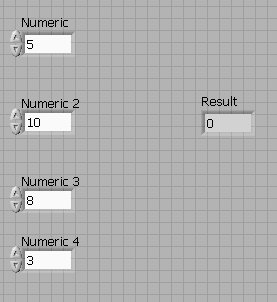
- 2.Now you are going to create the user interface in the front panel and it will look like the Front Panel above.
- 3.Make sure your cursor is in the front panel. You are going to add the four values called Numeric, Numeric 2, Numeric 3, and Numeric 4. These are input values used by the program and LabVIEW calls them controls. To add these to your front panel right click in the front panel and the controls window will come up. Click on Express»Num Ctrls and a window will come up, titled “Numeric Controls” containing some icons. You want to drag the one labeled “Num Ctrl” to the front panel. It will have the name of “Numeric” which is the default value. Position this control in the front panel like you see in the diagram above.
- 4.To add the other controls you will want to do the same exact thing dragging 3 of the “Num Ctrl” icons to the front panel. The names will be Numeric 2, Numeric 3, and Numeric 4 which is the default name. Notice that when you add a control to the front panel one also gets added to the block diagram. The front panel is what the users will see when they run the program and enter data into it.
- 5.In the diagram above notice that the 4 controls are on the left side of the screen and there is “Result” on the right side. “Result” is an output value that is computed by the program and is called an indicator. Generally, you want controls on the left side of the front panel and indicators on the right side. This simplifies the user interface for the user. Add an indicator to the front panel by right clicking on it and selecting Express»Num Inds and then dragging a “Num Ind” to the front panel. The name will be “Numeric 5” by default.
- 6.Notice that the name of the numeric indicator that you just created is “Numeric 5” and you need to change the name to “Result”. If you double click on the Numeric 5 label it will turn to a solid black background and you can type “Result”. Be sure to click somewhere in the front panel after you type “Result” and it will set the name. If you want to change the names of the controls to something like “a”, “b”, “c”, and “d” feel free to do that.
- 7.Notice that each of the four controls have values in them. When a control is created the default value is zero. To change this to a different value start by entering the value you want as the default in the control, then right click on the value and select Data Operations»Make Current Value Default. This means that every time the program is executed if the user does not enter a different value the value you entered in the control is used. Try setting the default value for the four numeric controls to the values shown above.
- 8.Now you have the front panel created and it is time to create the code to process the four controls and produce the Result indicator. The next page will show you how to do this.
Now it is time to create the programming code which, in LabVIEW, goes into the block diagram. As a reminder, we are trying to create a program that will calculate the equation below.

You have the user interface to read the value of the input values and to display the value of the equation after it is calculated. Now we have to add the code to compute the value of Result in the LabVIEW block diagram. The following steps will guide you through the development of this code.
- 1.Make sure your cursor is in the block diagram. If it is not visible you can press Ctrl-T and the front panel and block diagram will be tiled and, from there, you can move to the block diagram.
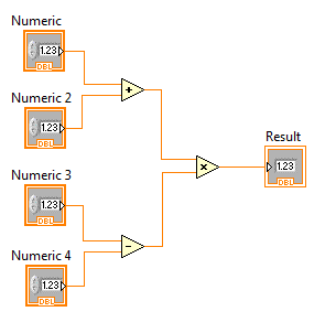
- 2.The code for the LabVIEW program that you are going to create is below.
You have the user interface to read the value of the input values and to display the value of the equation after it is calculated. Now we have to add the code to compute the value of Result in the LabVIEW block diagram. The following steps will guide you through the development of this code.
- 1.Make sure your cursor is in the block diagram. If it is not visible you can press Ctrl-T and the front panel and block diagram will be tiled and, from there, you can move to the block diagram.
- 2.The first thing that we need to do is to add the code to add “Numeric” and “Numeric 2”. In the block diagram, Right click and select Mathematics»Numeric and drag the addition operator to the block diagram.
- 3.LabVIEW passes data from one function to the next with wires and you will see these in the diagram above. The addition operator has two input values, which are called terminals in LabVIEW. You want to connect the terminals coming out of “Numeric” and “Numeric 2” to the input terminals of the addition operator. Move the cursor to the right of “Numeric” and the icon turns into a spool of wire. Hold the cursor and drag it to the top of the addition operator.
- 4.Now add a subtraction operator to the block diagram and position it down by “Numeric 3” and “Numeric 4” similar to the diagram above. After you do that you want to wire it just like you did with the addition operator.
- 5.The last icon to add is the multiplication operator between the addition and subtraction operator and wire the terminals coming out of the addition and the subtraction operator into it.
- 6.The final step is to wire the output of the multiplication into the Result indicator.
- 7.The program is now finished. You can tell if there are errors if the arrow between Edit and View is broken. A solid arrow means that there are no errors and a broken arrow means that you have errors in your code. If you have a broken arrow compare your program to the one listed above to see what is different.
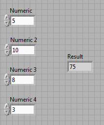
- 8.To run the program click on the solid arrow. If you don’t type in any values the default values will be used which means that the program will calculate 5+10 * 8-3 which is 75 and that will be displayed in the Result indicator. The front panel will look like this:
Your Second LabVIEW Program
One of the most common things that we do in computer science is to translate an algebraic equation into a form that is something that the computer will understand and can evaluate. We are going to use the following equation for this lesson:

In other programming language, like C++ or JAVA, we would write code that had formulas like this:
- y = (4 * pow(x,2) – 5) / (x-2);
Now, let’s compare this to the same program in LabVIEW. The approach that will be used to teach you programming in LabVIEW is a little different than others use. You are going to get a description of what you need to do and an opportunity to create the program on your own. If you need help the next page will guide you through the process of writing the program.
Here are the steps you want to perform in LabVIEW to compute this formula:
- 1.In a blank VI you want to go to the front panel and add a control and an indicator. The control should be named “x” and the indicator should be named “f(x)”. Remember that “f(x)” means that you are taking the value of x and evaluating the formula with that value.
- 2.In the block diagram you want to add the code that will evaluate this function in this order:
- 1.Take the value of x and square it.
- 2.Then multiply the squared value by 4.
- 3.Then subtract 5 from that value. That computes the numerator.
- 4.To compute the denominator, take the value of x straight out of the control just like you did in step “a)” and subtract 2 from it.
- 5.Then divide the numerator from step “c)” by the denominator in step “d)”.
- 6.Take the value from the division and wire it into the indicator.
LabVIEW Dataflow
Now we are going to take a closer look at the method that LabVIEW uses to pass data from one operation to another and some tools that are available for you to watch how a program is sent from say a control to a function or from a function to an indicator. We are going to use a tool that is provided by the LabVIEW system for monitoring a value as it comes out of an operator.
In a previous lesson we developed a program that performed addition, subtraction, and multiplication and looked like the program below.
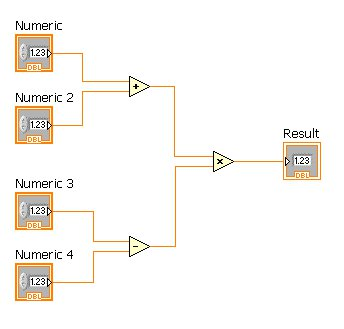
Make sure that you have LabVIEW up and running and the addition_subtraction program is open. In the block diagram you will see some icons at the top of the window that control the execution of your program. Below is a screenshot of those icons.

The first one is the arrow that you press when you want to run the program. The second one you can use to run the program continuously and you might want to try this with the addition_subtraction program. Every time you enter a new number in one of the controls, and then click outside of that control it will display the updated value. To stop a program that is running in continuous mode you can use the stop sign which is right next to the run continuous button. Right after the stop sign is a button that looks like two parallel lines. This one lets you pause the execution of the program when you start running it. If you do that it will allow you to monitor the values that are passed from one function to another by way of the wire. The light bulb will highlight the execution of the program showing the functions that are being executed. The 7th button, next to the last one, allows you to single step the execution of the program and we are going to use that in this lesson.
- 1.Make sure you have the addition_subtraction program open in LabVIEW. Press the button that looks like parallel lines. It is the 4th button from the left side as shown above. This will make the program stop after the first function is executed
- 2.Now, press the arrow to start the program running. It will stop execution on the addition function and that function will start flashing indicating that the program is paused at that point. It is important to know that when a function is flashing it has NOT executed it.
- 3.Now press the step over button, which is the next to last button in this sequence. The flashing cursor will move to the subtraction function indicating that it is the next to execute.
- 4.Press the step over button again and the flashing cursor will move to the multiplication function which indicates that both the addition and the subtraction have been done and now it is ready to perform the multiplication.
- 5.Before stepping through the multiplication we are going to perform what LabVIEW refers to as a probe meaning that we are going to see what values were passed to a function. If you move your cursor to the wire coming into the multiplication function you will see a “p” which means that you can probe that wire. Double click that wire and a probe window will come up showing the value entering from that wire. A number appears on the wire and the same number appears in a window with the value. You should experiment with this by clicking on other wires to see what values are passed on them.
- 6.It is important to note a few things here. First, if you step all the way through a program you will need to press the stop sign or the step out button to stop the program. The step out button is the very last button.
Experiment with the stepping and the probes so that you know how to monitor the execution of your program. These functions are very handy if you are performing any kind of programming from basic numeric processing to scientific sensor readings to MINDSTORMS® NXT and TETRIX® programming.
Monthly Loan Calculator
I want to buy a new laptop but I don’t have any money in my account. The only thing I can do is to borrow the money from the bank and pay it back each month. The only problem is that I need to know how much I am going to have to pay each month to keep from getting in trouble with the bank.
I found that there is a mathematical formula for doing all of this and so I am going to take what I am learning with LabVIEW and write a program. I bet that I can even come up with a really good looking user interface after I get the basics done. So let’s see what information I need to know about this bank loan and what the formula looks like.
There are three pieces of data that the bank wants to know:
- 1.The amount of money that you want to borrow, and we will call this “loan amount”.
- 2.The number of months until you have the loan paid off completely, and we will call this “months”
- 3.One thing that the bank really likes is the interest rate that you must pay on the loan. This will be given as a percent and we will call this “interest rate”
The formula for computing the monthly payment is shown below.

Computer programming can appear to be a very difficult task…and sometimes it becomes just that! If you think about the different parts of the program and temporarily ignore all of the rest it simplifies the project.
We need to break down the program into these steps:
- 1.Reading the three input values into controls
- 2.Computing the numerator of the equation
- 3.Computing the denominator of the equation
- 4.Checking both of these values with a calculator
- 5.Dividing the numerator by the denominator
- 6.Displaying the output in an indicator
You always want to start a LabVIEW program with the user interface in the front panel. This is because as you create the controls and indicators in the front panel they are also added to the code in the block diagram. Each of these steps will be explained here.
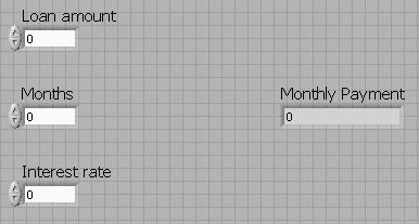
- 1.In the front panel window add the three controls on the left and the one indicator on the right. This will create the user interface and it should look something like the Front Panel below.
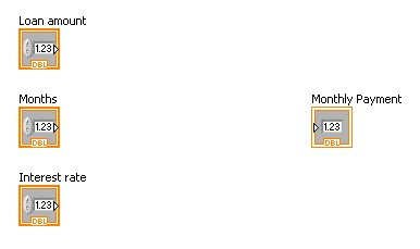
- 2.Now that the controls and indicators are on the front panel you will see that they are over in the block diagram and look like the program below.
- 3.You want to add the code to calculate the numerator to the block diagram. The block diagram now looks like the block diagram shown below.
- 4.You should then test the program now to make sure that the numerator is calculated correctly. Enter a loan amount of 2000, the rate is 5.5 (which is 5.5%), and the number of months is 12. You should get 9.6837 as the numerator and the program is displaying this in the monthly payment indicator.
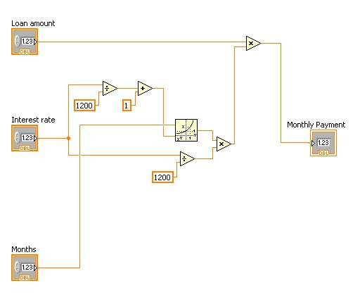
- 5.Now add the code to compute the denominator. The wire coming feeding into the Monthly Payment indicator is wired into the multiplication from the calculation of the numerator. You want to delete that wire when you add the following code. The final program should look like the image below.
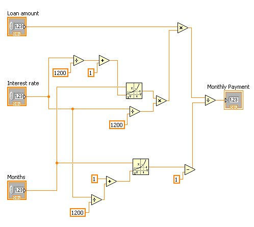
- 6.You are done! But first, check the program with this data to make sure it works ok. Here is the data to test your program.
| Loan Amount | Interest Rate | Months | Monthly Payment |
|---|---|---|---|
| $2000 | 5.5% | 12 | $171.67 |
| $25000 | 7.0% | 60 | $495.03 |
| $100000 | 5.0% | 120 | $1060.70 |
Case Structures
Many times when we are developing a computer program we have to make decisions and execute one set of code if a condition is true and another set of code if the condition is false. As an example, say we need to calculate the square root of a number. We have to make sure that the number is not negative since the square root of a negative number is undefined. Now, later you will learn how we can change the representation of a number from double to complex and, in this case, we would not have to verify that the number was not negative since the square root of a negative number is a complex number.
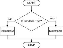
We will start with a flowchart that shows how a case structure is going to work.
You will notice that a condition is tested and either statement1 or statement2 will be executed. It is really important to note that never will both condition 1 and condition 2 be executed. This can be expanded if necessary to include more than just one statement for each condition and that is what we will be showing in an example. We are going to go through a program to show how to use case structures. It is going to take a number entered into a control and either calculate the square root of the number if it is greater than or equal to zero, or it will print a message if the number is negative and you can’t find the square root of it. Here are the steps for this.
- 1.Open a blank VI.
- 2.Switch over to the block diagram. Many times you will want the front panel and the block diagram to both be shown on the screen and you can do this by pressing Ctrl-t.
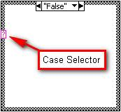
- 3.Now you want to add a case structure and you do this by going to the functions palette by right-clicking on the block diagram and selecting “Programming” > “Structures” and dragging a Case Structure to the Block Diagram. You want to make the Case Structure big enough to hold some other icons. It should look like the image above.
- 4.Notice that there is a pink question mark on the left and that is the Case value. This is where you will wire in the condition. For this example it will test to see if the number is greater than or equal to zero and we do that soon.
- 5.Now you want to add a control to the front panel and then make sure that it is to the left of the case structure in the block diagram.
- 6.Then add a greater than or equal to zero operator in the block diagram to the right of the control. You can find this by going to the functions palette and selecting “Programming” > “Comparison” and dragging the Greater or Equal to Zero icon to the block diagram.
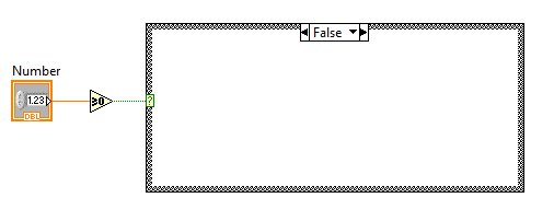
- 7.Now you have to connect wires to the control, the comparison operator, and the case structure. Your Block Diagram should look like the image above.
- 8.The output of the case structure is either going to be the square root of the number, if the number is greater than or equal to zero, or it is going to be infinity if the number is less than zero. Add an indicator to the front panel, change the name of it to Square Root Value, and then over in the block diagram position it to the right of the case structure.
- 9.Now you need to add the code to each of the cases. We will start with the false case which means that the number is not greater than or equal to zero. Add a positive infinity constant to the case diagram. You can find this in the functions palette under “Mathematics” > “Numeric” and drag the +Inf icon inside the block diagram. It should be fairly close to the indicator that you added labeled “Square Root Value”. Run a wire from the infinity constant, through the boundary of the Case Structure, and to the Square Root Value indicator.
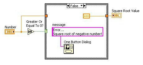
- 10.The message “Error…Square root of negative number!” is going to display on the screen in a one button dialog box. Go to the functions palette and select “Programming” > “Dialog & User Interface”, and drag a “One Btn Dialog” inside the Case Structure. To create the message you want to create a constant on the One Btn Dialog that says “message”. Type “Error…Square root of negative number!”. The false case should look similar to the image above.
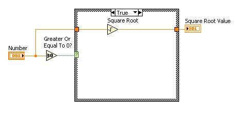
- 11.The true case, which indicates that the number is greater than or equal to zero, is much easier because you simply take the number that was entered, run it into a square root function and then the output of it to the Square Root Value indicator. Switch to the true case by clicking on the small arrow next to “False” at the top of the case structure and select “True”. It will be blank because there is no code for the true condition yet.
- 12.Add a Square Root function to the true case and you can find it in the Functions palette, “Mathematics” > “Numeric” > “Square Root”. To wire the true case you want to run a wire from the number, through the case structure boundary to the square root function. Then, run the output of the square root function through the boundary of the case structure and then to the Square Root Value indicator. It should look like the Block Diagram below.
- 13.Now you can test the program and you should use some positive numbers, some negative numbers, and a zero to make sure everything works okay.
Introduction to Loops
One of the best things that a computer can do is to perform the same operations over and over until a condition has been reached. That condition may be something like a counter reaching a certain number, or reading data from a file until all of the data has been read, or until a certain computed value has been reached. This tutorial is going to show you how to perform a loop in LabVIEW.
You have a couple of options to choose from here. If you know nothing about loops, select the first link which is titled Explain loops using LabVIEW. If you already know what while or for loops are and want to do some exercises using some real problems you can select the second or third link – the second link shows how to calculate the square root with a for loop and the third link shows how to calculate it using the while loop. After you go through these links you may want something that is a little more complex and the fourth gives you a problem to solve using loops.
Loops are a very important part of software applications and software developers (which you may become!) must know how to use them right. It is really easy to create a program that runs just fine, produces the correct results, but is not written correctly. The more code you develop the better you become in developing clean code. Practice!
Now it is time to introduce the basic idea of loops in a computer program and specifically for LabVIEW. Loops are present in every programming language and the more practice you get with them the better you get at developing code. Examples of loops in LabVIEW might range from having a LEGO® NXT robot move around the four walls in a room repeating the same operations for each wall or we might want to collect samples from water with salt slowly added using a temperature sensor until the temperature stops changing in temperature. Each of these will require a loop and this lesson will teach you how to do these.
The basic definition of a loop is that we are going to repeat a set of code UNTIL either…
- 1.The code has been executed a certain number of times
- 2.Or a certain condition occurs such as the user entering some key, reaching the end of a data file, or maybe even an error that has happened causing the program to stop
Every loop in every programming language has a basic set of principles which are:
- A set of code is repeated multiple times and it is VERY important to make it as efficient as possible.
- An iteration is one time through the code in the loop.
- A loop counter keeps track of the iterations made. It is an integer value that always starts at zero.
- A termination test is performed each time thru the loop and is a Boolean value testing to see if the loop should be terminated or not.
We have two loops in LabVIEW which are the for and the while loop and when you are starting out it is sometimes difficult choosing between the two of them. Here are some guidelines on selecting the right loop:
- 1.If you are performing a set of code a set number of times you want to use a for loop. The number of times can either be a constant, a control, or any other method of storing an integer in a LabVIEW program.
- 2.If you are performing a set of code until the user presses a key, a sensor reads a value that triggers some condition, or an error condition occurs you want to use a while loop.
- 3.Say you were executing a set of code a set number of times, the code is in a for loop, and you needed to check for some error condition. In addition to the for loop executing until a count is reached you can also terminate the execution on some other conditions.
- 4.Generally, you don’t want to use a while loop in a count control loop. It is cleaner to use a for loop.
Now we need to look at the pseudo code of a for loop and a while loop because in the next section the LabVIEW code will be presented for each of these. The more you practice with the programming the better you will become at visualizing the execution of your program which is a very important part of computer science.
Here is the pseudo code for a for loop that will print a certain number of random numbers ranging from 0 to 1. The user specifies the number of numbers to be printed. Note that we are using a for loop for this example since it is easy to construct a for loop when we are counting.
- 1.Read number_to_be_printed
- 2.For i=0 to number_to_be_printed
- 3.print random_number
- 4.End for
The while loop is going to print random numbers until the user presses the stop button and looks like this:
- 1.STOP = false
- 2.While STOP is false
- 3.print random_number
- 4.Check if stop button has been pressed and set STOP to true if it has
- 5.End while
The next section will show you the code for each of these and then move into some more practical applications of them.
LabVIEW While Loops
Now we are going to quickly go through the steps to create a while loop in LabVIEW.
- 1.We are going to print random numbers until the user clicks on a stop button. The Functions palette may not be visible and you can display it by right-clicking any blank space on the block diagram. Add an indicator and a random number function in the block diagram. The random number function can be found in the functions palette by clicking on programming –> numeric –> random number and dragging it onto the block diagram. The block diagram should look like what is below.

- 1.Select the while loop by clicking on Programming»Structures»For loop in the Functions palette. If you need help in finding it, below is a diagram showing the structure’s palette.
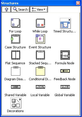
- 3.Drag the while loop onto the block diagram, then use the cursor to drag a selection rectangle around the code in the block diagram that is to be repeated.
- 4.When you release the mouse button, a while loop boundary encloses the section you have selected.
- 5.Place a Stop button on the front panel. You can find this under Express –> Buttons –> Stop Button place it inside the while loop and wire the Stop Button to the Loop Condition Terminal. It should look like what is below.

- 6.The conditional terminal, shown below, defines when the loop stops. There are two settings for the conditional terminal: Continue if True and Stop if True. When set to Continue if True, the while loop runs only if a Boolean value of true is sent to the terminal. If the conditional terminal is set to Stop if True, and a Boolean value of true is sent to the conditional terminal, the loop halts execution. The Stop if True is the one that we have in our program now.
- 7.When the Stop button is pressed, a true value is passed to the conditional terminal causing the while loop to stop execution.
- 8.The iteration terminal is an output terminal that contains the number of completed iterations. The iteration count always starts at zero. During the first iteration, the iteration terminal returns 0. You want to include a new indicator, label it as “Loop number”, and wire the iteration terminal to the indicator. It will look like what is below.

- 9.It is time to run the program and test to see if it works ok. Click on the run arrow and it should start printing random numbers and the counter should be printing numbers very quickly. Remember that the program will run until the Stop button is pressed. Here is a diagram of what your while loop may look like the while loop below.
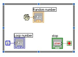
There are two places to go from here. The first, if you want, you can stop this tutorial on loops. Now, if you want to learn some really cool things that you can do with your while loop to include a dial where you can slow down the generation of the random numbers there is a link below that will do that. Have fun!
For Loops
Now it’s time to quit talking about the theory behind loops and get into the code. In this lesson we are going to go through the basics of creating a for loop. Remember that a for loop in LabVIEW is used best when you are wanting to perform a set of code a certain number of times. Say we wanted to do something like collect 100 samples from a sensor that we have connected to our PC. In the following example the LabVIEW code that will collect the data is “Code”. On the left side we have the for loop in LabVIEW and on the right we have the flow chart.
Note that the loop counter starts at 0 and when it is equal to the value of N the loop will stop. If we print the value of the loop counter, which you will see how to do, you will get the value of 100.
Now we are going to quickly go through the steps to create a for loop in LabVIEW.
- 1.Create a blank VI by selecting File»New VI.
- 2.We are going to print 100 random numbers so you want to create code to do that first. The Functions palette may not be visible and you can display it by right-clicking any blank space on the block diagram. Add an indicator and a random number function in the block diagram. The random number function can be found in the functions palette by clicking on programming –> numeric –> random number and dragging it onto the block diagram. The block diagram should look like the following image.

- 3.Select the for loop by clicking on Programming –> Structures –> For loop in the Functions palette. Drag the for loop onto the block diagram, then select all the code that you just created to print a random number WITHOUT releasing the left mouse button. This will add the code to print the random number to the for loop. If you need help finding the for loop, refer to the following diagram showing the While loop in the structures palette.
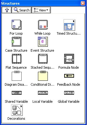
- 4.A for loop contains a count terminal. The count terminal dictates how many times the subdiagram is executed and looks like what is shown below, on the for loop.

- 5.Right-click on the count terminal and Create Constant to link the count terminal with a numeric value. Set the value to 100. Then wire the count terminal to the constant. It should look like what is shown below.
- 6.By inserting 100 into the numeric constant, the for loop executes 100 times before stopping.

- 7.The last thing we are going to do is to print the value of the count terminal for every iteration of the loop. This is useful because you can watch the program execute. Add an indicator inside the for loop and wire it like what is shown below.

- 8.Now you have your first for loop. Make sure it looks similar to this diagram. Yours may be slightly different because you may have the icons in different locations.
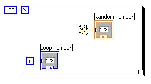
- 9.When you run the program it is going to print things very quickly. You can clock on the “Highlight Execution” button which is 4 buttons to the right of the run arrow to watch the numbers and the counter print slowly. You are done!
Shift Registers
Many times you will be creating a program with loops and you need to use data from the previous iteration. As an example, say you are writing a program that will move the NXT robot counting the number of times a particular object is found on the ground as you move around the four corners of the room. A for loop going from 0 to 3 works for the 4 corners but you need to retain the counter as the object is found.
In LabVIEW, you can use shift registers, which allows you to pass a value from one to the next iteration. If you know programming languages such as C++ or JAVA you may be familiar with static variables which are used to pass values from one loop iteration to the next.
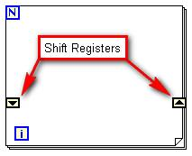
Above is a block diagram showing what you are going to create in LabVIEW.
Data comes into the loop by way of the shift register on the left side of the for loop and is passed to the next iteration of the loop through the shift register on the right side of the for loop. Below is another diagram that shows more detail about the passing of data in the shift register.
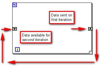
Now we are going to write a LabVIEW program that will calculate the sum of the numbers from 1 to 10 using a shift register in a for loop. If you know C++ or JAVA, here is the same program in C++.
- int i, n, sum;
- n=11;
- sum=0;
- for (i=0; i<n; i++)
- {
- sum = sum + i;
- }
- cout << sum << endl;
- 1.Start with a blank VI and add a for loop over in the block diagram.
- 2.Now we are going to add the shift register to the for loop. Move the cursor to the left border of the for loop. If you are slow enough when you are moving the cursor the words “for loop” will come up. Right click as soon as you are on the border. You will know that you are in the right location because a set of operations for the for loop will be there instead of the function palette. Select “Add Shift Register”
- 3.The sum must start off at zero and then add 1, then add 2, and so on until we reach 10. To initialize the shift register you right click on the left shift register and create a constant with zero in it. To do that right click in the block diagram and select Express –> Arithmetic and Comparison –> Express Numeric and drag the “Num Constant” icon to the left of the shift register. Wire the constant into the shift register.
- 4.Remember that for loops in LabVIEW go from 0 to N-1 where N is the value in the count terminal which looks like this:

Now you want to set the count terminal to 11 because you want the numbers from 0 to 10. Move the cursor up next to the count terminal, right click and select “create constant”. Set the constant to 11.

- 5.The iteration terminal of the for loop, which looks like the icon above, provides the current loop count going from 0 to 10 and will change every time through the loop. We want the value from the shift register, which will have the previous sum of numbers added to the count terminal giving us the current sum. As an example, say we have been through the loop 4 times and it has summed 0+1+2+3 which is 6. We are going to add together the 6 plus the current count terminal, which will have the value of 5 in it, giving 11. To do this add an “addition” function to the block diagram, wire the shift register on the left side of the for loop to one input and the count terminal to the other input. Wire the output to the shift register on the right side of the for loop.
- 6.Now we have the for loop calculating the sum of 0..10 but we need to print that sum after the loop has finished. To do that we add an indicator outside of the for loop to the right of it and wire the shift register on the right side of the for loop to this indicator.
- 7.You have a very basic loop with a shift register and you want to make sure that when it is run it produces the output of 55 since the sum of the numbers from 0..10 is 55. If you want to see what your program should look like, below is a version of the program. Yours may be different with wired and nodes in different locations.
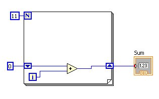
In one of the exercises in this tutorial there is a program to compute the square root of a number and that will use a shift register in a while loop. The while loop is used for this problem because we will compute a new estimate of the square root from the value computed in the previous iteration and pass the new value in the shift register.
Square Root Calculator
This will be the final program that you will be doing in the Basic LabVIEW course. It will be calculating the square root of a number, X, and will be using a shift register to do so. You will have the option of doing the program completely on your own after the flowchart is shown below.
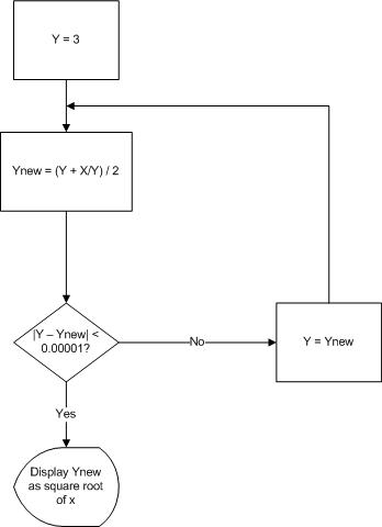
Let’s go over a few items in the flowchart to better understand what is being sent through the shift register. You can then try to write the LabVIEW code yourself before the code is given to you or you can go straight to the code and enter it from the step-by-step instructions.
- The square root is going to be calculated in a while loop that has a shift register. The while loop will have a termination test and will be covered below.
- The value of X is the number which we are finding the square root of and this value will never change throughout the program. Therefore, we don’t want to pass it through the shift register but we do want to read it outside of the loop and pass the value through the loop boundary into the loop.
- The value of Y is initially set to 3 and used inside the loop for calculating a new value, Ynew. This means that upon each iteration of the loop the newly calculated value of Ynew is sent back to the loop and picked up as Y. This is probably the most difficult part of a shift register and it may take a little getting used to. Basically you want to take an initial value, calculate a new value, and send the new value back to through the loop.
- The loop keeps iterating until the absolute value of the difference of Y and Ynew is less than or equal to 0.00001. When the difference between those two values is less than 0.00001 the square root value is very accurate and the loop should stop. In LabVIEW we have to wire this condition test into the stop condition.
- After exiting from the while loop we want to print the square root of X and this is stored in Ynew. This means that we run a wire through the while loop boundary to an indicator outside of the loop. The wire takes the value of Ynew and sends it to the indicator. The user will see two things on the screen: a control that has the value, X in the flowchart, that they want to find the square root of and an indicator, Ynew in the flowchart, which has the square root of x.
See if you can write the LabVIEW program for this or you can jump straight to the code. You may find that seeing the code teaches you more than trying to figure it out yourself.
When you write the square root program it requires you to think about the code structure. One advantage of LabVIEW is that you get away from the syntax of the programming language and you get to think about the logic of the program. The most difficult part of LabVIEW programming is that it requires you to know about the dataflow programming but as soon as you write your first program this gets much easier. Let’s start with the front panel of the square root program.
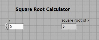
In the front panel image above, you can see that there is one control on the left which has the label of “x”. Then, on the right, is one indicator which has the label of “square root of x”. Now let’s see what the block diagram looks like.
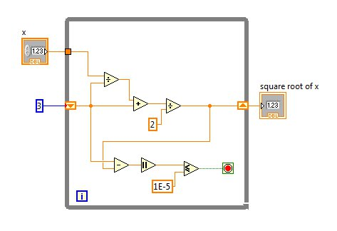
Here are the steps that you need to construct the block diagram.
- 1.Start with a blank VI and make sure that you have added the control and the indicator and that the names have been changed as shown on the front panel diagram above.
- 2.Add a while loop to your block diagram. You want to make the while loop fairly large so that the code can be added. Make sure that you don’t wire the control or the indicator yet. That will come in a few steps.
- 3.We need to add a shift register to the while loop and you do that by right clicking on the while loop boundary and select “add shift register”.
- 4.Now you are going to add the initial value of y. In the previous page we mentioned that Y is the value that enters the shift register, the value of Ynew is calculated, and the value of Ynew is sent out of the shift register to the next iteration of the loop. We need to initialize the value of Y to 3 and you can do that by adding a numeric constant outside of the while loop and you do that by right clicking in the block diagram and selecting Mathematics — Numeric –> Numeric Constant. Then make sure that the value in the constant is 3.
- 5.Wire the constant to the shift register and make sure it looks like the block diagram above.
- 6.The top condition is taking the previous value of Y, subtracting the new value of Y from it, taking the absolute value, and comparing that value to 0.00001. The absolute value function is obtained by right clicking on the block diagram and selecting Mathematics –> Numeric. The less than or equal comparison operator is located at Programming –> Comparison –> Less than or equal.
- 7.Add the remaining functions to the block diagram and wire everything like is shown in the block diagram above.
- 8.Now it is time to run the program. Enter a 2 in the control labeled X and press the run arrow. You should get 1.1421 as the output.
Congratulations! You have a complete square root calculator program! If you want to do more with this program, in the next exercise you will modify the square root program to compute the Nth root of a number.

