
CCNA Tutorial
Last updated on 12th Oct 2020, Blog, IOT and Networking, Tutorials
What is CCNA?
CCNA stands for Cisco Certified Network Associate. It is a certification course offered by Cisco.
CCNA improves your understanding of the internet working and how different network topologies work together to form a network.
What is Cisco?
Cisco is the American multinational technology company in the centre of California. It is the king of routing, switching, and security. Most of the companies use Cisco devices in their daily routine.
Cisco developers manufacture and sell networking hardware, telecommunication equipment, and other high-technology services and products.
Why CCNA?
- CCNA validates the ability to understand, operate, configure, and troubleshoot routed and switched network.
- It helps to resolve a customer’s problem more efficiently.
- Once you are CCNA certified, you can get a higher salary.
- It teaches the candidate how to create a point-point connection.
- It explains how to construct network addresses.
Why to acquire a CCNA certification?
- 1. The certificate validates a professional’s ability to understand, operate, configure and troubleshoot medium-level switched and routed networks. It also includes the verification and implementation of connections via remote sites using WAN.
- 2. It teaches the candidate how to create point-to-point network
- 3. It teaches about how to meet users requirement by determining the network topology
- 4. It imparts on how to route protocols in order to connect networks
- 5. It explains about how to construct network addresses
- 6. It explains on how to establish a connection with remote networks.
- 7. The certificate holder can install, configure and operate LAN and WAN services for small networks
- 8. CCNA certificate is a pre-requisite for many other Cisco certification like CCNA Security, CCNA Wireless, CCNA Voice, etc.
- 9. Easy to follow study material available.
Types of CCNA certification
To secure CCNA. There are basically two approaches as shown below.
- 1. ICND1 Exam and ICND2
- 2. Combined CCNA Exam
As we discussed earlier the validity for any CCNA certificate last for three years.
| Exam Code | Designed for | Duration and number of questions in exam | Exam Fees |
|---|---|---|---|
| 100-101 ICND1 | Entry-level Network Technician | 90 mins exam duration50-60 questions | $150 ( for different country price may vary) |
| 200-101 ICND2 | Experienced Network Technician | 75 mins exam duration50-60 questions | $150 ( for different country price may vary) |
| 200-120 CCNA | Experienced Network Technician | 90 mins exam duration50-60 questions | $295 ( for different country price may vary) |
Beside this certification, new certification course enrolled by CCNA include-
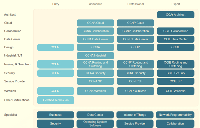
- 1. CCNA Cloud
- 2. CCNA Collaboration
- 3. CCNA Switching and Routing
- 4. CCNA Security
- 5. CCNA service provider
- 6. CCNA DataCenter
- 7. CCNA Industrial
- 8. CCNA Voice
- 9. CCNA Wireless
The candidate to a CCNA certification can also prepare for the exam with the help of the CCNA boot camp.
To complete CCNA exam successfully. These are the topics one must be thorough of TCP/IP and the OSI model, subnetting, IPv6, NAT (Network Address Translation) and wireless access.
Subscribe For Free Demo
Error: Contact form not found.
What does the CCNA course consist of
- The ICND1 encompasses of topics like IP routing technologies, IP services (NAT, ACLS, DHCP), network device security, IPv6, LAN switching technologies, etc.
- The ICND2 encompasses of topics like IP routing technologies, IP services (FHRP, syslog, SNMP v2 and v3), LAN switching technologies and WAN technologies.
- The CCNA combined exam covers all the topics in ICND1 and ICND2. It covers topics on installation, operation and trouble shoot.
New changes in the current CCNA exam includes,
- Deep understanding of IPv6
- CCNP level subjects as HSRP, DTP, EtherChannel
- Advanced troubleshooting techniques
- Network design with supernetting and subnetting
Eligibility Criteria for Certification
For certification, no degree is required. However, preferred by some employers.
Internet local area networks
An internet local area network consists of a Computer Network that interconnects computers within a limited area like office, residence, laboratory, etc. This area network includes WAN, WLAN, LAN, SAN, etc.
Among these WAN, LAN and WLAN are most popular ones. In this study guide, you will learn how the local area networks can be established using these network system.
Understanding the Need for Networking
What is a Network?
A network is defined as a two or more independent devices or computers that are linked to share resources (such as printers and CDs), exchange files, or allow electronic communications.
For example, the computers on a network may be linked through telephone lines, cables, satellites, radio waves, or infrared light beams.
The two very common types of network include:
- 1. Local Area Network (LAN)
- 2. Wide Area Network (WAN)
From OSI reference model, the layer 3, i.e., Network layer is involved in networking. This layer is responsible for packet forwarding, routing through intermediate routers, recognizing and forwarding local host domain messages to transport layer (layer 4), etc.
The network operates by connecting computers and peripherals using two pieces of equipment include routing and switches. If two devices or computers are connected on the same link, then there is no need for a network layer.
Internetworking Devices used on a network
For connecting internet, we require various internetworking devices. Some of the common devices used in building up Internet are.
- 1. NIC: Network Interface Card or NIC are printed circuit boards that are installed in workstations. It represents the physical connection between the workstation and network cable. Although NIC operates at the physical layer of the OSI model, it is also considered as a data link layer device. Part of the NIC’s is to facilitate information between the workstation and the network. It also controls the transmission of data onto the wire
- 2. Hubs: A hub helps to extend the length of a network cabling system by amplifying the signal and then re-transmitting it. They are basically multiport repeaters and not concerned about the data at all. The hub connects workstations and sends a transmission to all the connected workstations.
- 3. Bridges: As network grow larger, they often get difficult to handle. To manage these growing network, they are often divided into smaller LANs. These smaller LANS are connected to each other through bridges. This helps not only to reduce traffic drain on the network but also monitors packets as they move between segments. It keeps the track of the MAC address that is associated with various ports.
- 4. Switches: Switches are used in the option to bridges. It is becoming the more common way to connect network as they are simply faster and more intelligent than bridges. It is capable of transmitting information to specific workstations. Switches enable each workstation to transmit information over the network independent of the other workstations. It is like a modern phone line, where several private conversation takes place at one time.
- 5. Routers: The aim of using a router is to direct data along the most efficient and economical route to the destination device. They operate at Network layer 3, which means they communicate through IP address and not physical (MAC) address. Routers connect two or more different networks together, such as an Internet Protocol network. Routers can link different network types such as Ethernet, FDDI, and Token Ring.
- 6. Brouters: It is a combination of both routers and bridge. Brouter act as a filter that enables some data into the local network and redirects unknown data to the other network.
- 7. Modems: It is a device that converts the computer-generated digital signals of a computer into analog signals, traveling via phone lines.
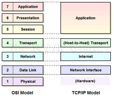
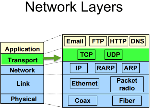
Understanding TCP/ IP layers
TCP/IP stands for Transmission Control Protocol/ Internet Protocol. It determines how a computer should be connected to the Internet and how data should be transmitted between them.
- TCP: It is responsible for breaking data down into small packets before they can be sent on the network. Also, for assembling the packets again when they arrive.
- IP (Internet Protocol): It is responsible for addressing, sending and receiving the data packets over the internet.
Below image shows TCP/IP model connected to OSI Layers..
Understanding TCP/IP Internet Layer
To understand TCP/IP internet layer we take a simple example. When we type something in an address bar, our request will be processed to the server. The server will respond back to us with the request. This communication on the internet is possible due to the TCP/IP protocol. The messages are sent and received in small packages.
The Internet layer in the TCP/IP reference model is responsible for transferring data between the source and destination computers. This layer includes two activities
- 1. Transmitting data to the Network Interface layers
- 2. Routing the data to the correct destinations
So how this happen?
Internet layer packs data into data packets referred as IP datagrams. It consists of source and destination IP address. Beside this, IP datagram header field consists of information like version, header length, type of service, datagram length, time to live, and so on.
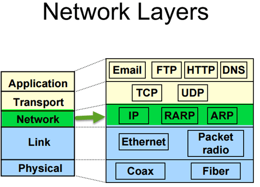
In network layer, you can observe network protocols like ARP, IP, ICMP, IGMP, etc. The datagram are transported through network using these protocols. They each resemble some function like.
- The Internet Protocol (IP) is responsible for IP addressing, routing, the fragmentation and reassembly of packets. It determines how to route message on the network.
- Likewise, you will have ICMP protocol. It is responsible for diagnostic functions and reporting errors due to the unsuccessful delivery of IP packets.
- For the management of IP multicast groups, IGMP protocol is responsible.
- The ARP or Address Resolution Protocol is responsible for the resolution of the Internet layer address to the Network Interface layer address such as a hardware address.
- RARP is used for disk less computers to determine their IP address using the network.
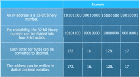
The image below shows the format of an IP address.
Understanding TCP/IP Transport Layer
The transport layer also referred as Host-to-Host Transport layer. It is responsible for providing the Application layer with session and datagram communication services.
The main protocols of the Transport layer are User Datagram Protocol (UDP) and the Transmission Control Protocol (TCP).
- TCP is responsible for the sequencing, and acknowledgment of a packet sent. It also does the recovery of packet lost during transmission. Packet delivery through TCP is more safe and guaranteed. Other protocols that falls in the same category are FTP, HTTP, SMTP, POP, IMAP, etc.
- UDP is used when the amount of data to be transferred is small. It does not guarantee packet delivery. UDP is used in VoIP, Videoconferencing, Pings, etc.

Get On-Demand CCNA Training for Beginners to Advance Your Career
- Instructor-led Sessions
- Real-life Case Studies
- Assignments
Network Segmentation
Network segmentation implicates splitting the network into smaller networks. It helps to split the traffic loads and improve the speed of the Internet.
Network Segmentation can be achieved by following ways,
- 1. By implementing DMZ (demilitarised zones) and gateways between networks or system with different security requirements.
- 2. By implementing server and domain isolation using Internet Protocol Security (IPsec).
- 3. By implementing storage based segmentation and filtering using techniques like LUN (Logical Unit Number) masking and Encryption.
- 4. By implementing DSD evaluated cross-domain solutions where necessary
Why Network Segmentation is important
Network Segmentation is important for following reasons,
- Improve Security– To protect against malicious cyber attacks that can compromise your network usability. To detect and respond to an unknown intrusion in the network
- Isolate network problem– Provide a quick way to isolate a compromised device from the rest of your network in case of intrusion.
- Reduce Congestion– By segmenting the LAN, the number of hosts per network can be reduced
- Extended Network– Routers can be added to extend the network, allowing additional hosts onto the LAN.
VLAN Segmentation:
VLANs enables an administrator to segment networks. Segmentation is done based on the factors such as project team, function or application, irrespective of the physical location of the user or device. A group of devices connected in a VLAN act as if they are on their own independent network, even if they share a common infrastructure with other VLANs. VLAN is used for data-link or internet layer while subnet is used for Network/IP layer. Devices within a VLAN can talk to each other without a Layer-3 switch or router.
The popular device used for segmenting are a switch, router, bridge, etc.
Subnetting
Subnets are more concerned about IP addresses. Subnetting is primarily a hardware-based, unlike VLAN, which is software based. A subnet is a group of IP address. It can reach any address without using any routing device if they belong to the same subnet.
Few things to consider while doing network segmentation
- 1. Proper user authentication to access the secure network segment
- 2. ACL or Access lists should be properly configured
- 3. Access audit logs
- 4. Anything that compromises the secure network segment should be checked- packets, devices, users, application, and protocols
- 5. Keep watch on incoming and outgoing traffic
- 6. Security policies based on user identity or application to ascertain who has access to what data, and not based on ports, IP addresses, and protocols
- 7. Do not allow the exit of cardholder data to another network segment outside of PCI DSS scope.
Packet Delivery Process
So far we have seen different protocols, segmentation, various communication layers, etc. Now we are going to see how the packet is delivered across the network. The process of delivering data from one host to another depends on whether or not the sending and receiving hosts are in the same domain.
A packet can be delivered in two ways,
- 1. A packet destined for a remote system on a different network
- 2. A packet destined for a system on the same local network
If the receiving and sending devices are connected to the same broadcast domain, data can be exchanged using a switch and MAC addresses. But if the sending and receiving devices are connected to a different broadcast domain, then the use of IP addresses and the router is required.
Layer 2 packet delivery
Delivering an IP packet within a single LAN segment is simple. Suppose host A wants to send a packet to host B. It first needs to have an IP address to MAC address mapping for host B. Since at layer 2 packets are sent with MAC address as the source and destination addresses. If a mapping does not exist, host A will send an ARP Request (broadcast on the LAN segment) for the MAC address for IP address. Host B will receive the request and respond with an ARP reply indicating the MAC address.
Intrasegment packet routing
If a packet is destined for a system on the same local network, which means if the destination node are on the same network segment of the sending node. The sending node addresses the packet in the following way.
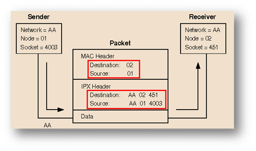
- The node number of the destination node is placed in the MAC header destination address field.
- The node number of the sending node is placed in the MAC header source address field
- The full IPX address of the destination node is placed in the IPX header destination address fields.
- The full IPX address of the sending node is placed in the IPX header destination address fields.
Layer 3 Packet delivery
To deliver an IP packet across a routed network, it requires several steps.
For instance, if host A wants to send a packet to host B it will send the packet in this ways
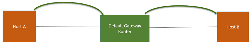
- 1. Host A sends a packet to its “default gateway” (default gateway router).
- 2. To send a packet to the router, host A requires to know the Mac address of the router
- 3. For that Host A sends an ARP request asking for the Mac address of the Router
- 4. This packet is then broadcast on the local network. The default gateway router receives the ARP request for MAC address. It responds back with the Mac address of the default router to Host A.
- 5. Now Host A knows the MAC address of the router. It can send an IP packet with a destination address of Host B.
- 6. The packet destined for Host B sent by Host A to the default router will have the following information,
- 6.1 Information of a source IP
- 6.2 Information of a destination IP
- 6.3 Information of a source Mac address
- 6.4 Information of a destination Mac address
- 7. When the router receives the packet, it will end an ARP request from host A
- 8. Now Host B will receive the ARP request from the default gateway router for the host B mac address. Host B responds back with ARP reply indicating the MAC address associated with it.
- 9. Now, default router will send a packet to Host B
Intersegment packet routing
In the case where two nodes residing on different network segments, packet routing will take place in the following ways.
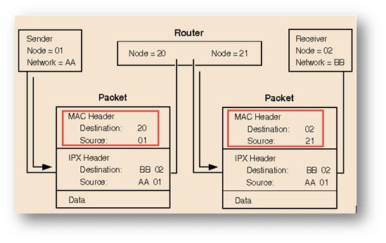
- In the first packet, in the MAC header place the destination number “20” from the router and its own source field “01”. For IPX header place the destination number “02”, source field as “AA” and 01.
- While in the second packet, in the MAC header place the destination number as “02” and source as “21” from the router. For IPX header place the destination number “02” and source field as “AA” and 01.

Enroll in CCNA Training & Certification Course From Real-Time Experts
Weekday / Weekend BatchesSee Batch DetailsWireless Local Area Networks
Wireless technology was first introduced in the 90’s. It is used to connect devices to a LAN. Technically it is referred as 802.11 protocol.
What is WLAN or Wireless Local Area Networks
WLAN is a wireless network communication over short distances using radio or infrared signals. WLAN is marketed as a Wi-Fi brand name.
Any components that connect to a WLAN is considered as a station and falls into one of two categories.
- 1. Access point (AP): AP transmit and receive radio frequency signals with devices able to receive transmitted signals. Usually, these devices are routers.
- 2. Client: It may comprise a variety of devices like workstations, laptops, IP phones, desktop computers, etc. All work-stations that are able to connect with each other are known as BSS ( Basic Service Sets).
Examples of WLAN includes,
- 1. WLAN adapter
- 2. Access point (AP)
- 3. Station adapter
- 4. WLAN switch
- 5. WLAN router
- 6. Security Server
- 7. Cable, connectors and so on.
Types of WLAN
- Infrastructure
- Peer-to-peer
- Bridge
- Wireless distributed system
Major difference between WLAN and LANs
- 1. Unlike CSMA/CD (carrier sense multiple access with collision detect), which is used in Ethernet LAN. WLAN uses CSMA/CA (carrier sense multiple access with collision avoidance) technologies.
- 2. WLAN uses Ready To Send (RTS) protocol and Clear To Send (CTS) protocols to avoid collisions.
- 3. WLAN uses a different frame format than wired Ethernet LANs use. WLAN requires additional information in the Layer 2 header of the frame.
WLAN Important Components
WLAN rely very much on these components for effective wireless communication,
- Radio Frequency Transmission
- WLAN Standards
- ITU-R Local FCC Wireless
- 802.11 Standards and Wi-Fi protocols
- Wi-Fi Alliance
Let see this one-by-one,
Radio Frequency Transmission
Radio frequencies range from the frequencies used by cell phones to the AM radio band. Radio frequencies are radiated into the air by antennas that create radio waves.
The following factor can influence radio frequency transmission,
- 1. Absorption– when radio waves bounce off the objects
- 2. Reflection– when radio waves strike an uneven surface
- 3. Scattering– when radio waves absorbed by objects
WLAN Standards
To establish WLAN standards and certifications, several organizations have stepped forward. Organization has set regulatory agencies to control the use of RF bands. Approval is taken from all the regulatory bodies of WLAN services before any new transmissions, modulations and frequencies are used or implemented.
These regulatory bodies include,
- Federal Communications Commission (FCC) for the United States
- European Telecommunications Standards Institute (ETSI) for Europe
While to define the standard for these wireless technologies you have another authority. These include,
- IEEE (Institute of Electrical and Electronic Engineers)
- ITU (International Telecommunication Union)
ITU-R Local FCC Wireless
ITU (International Telecommunication Union) co-ordinate spectrum allocation and regulations among all of the regulatory bodies in each country.
A license is not needed to operate wireless equipment on the unlicensed frequency bands. For instance, a 2.4 gigahertz band is used for wireless LANs but also by Bluetooth devices, microwave ovens, and portable phones.
WiFi protocols and 802.11 Standards
IEEE 802.11 WLAN uses a media access control protocol called CSMA/CA (Carrier Sense Multiple Access with Collision Avoidance)
A wireless distribution system allows the wireless interconnection of access points in an IEEE 802.11 network.
The IEEE (Institute of Electrical and Electronic Engineers) 802 Standard comprises a family of networking standards that cover the physical layer specifications of technologies from Ethernet to wireless. The IEEE 802.11 uses the Ethernet protocol and CSMA/CA for path sharing.
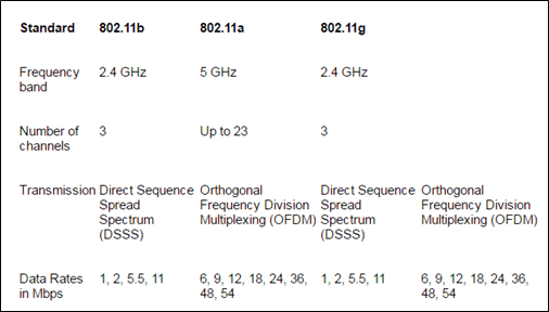
The IEEE have defined a various specification for WLAN services( as shown in table). For instance, 802.11g applies to wireless LANs. It is used for transmission over short distances at up to 54-Mbps in the 2.4 GHz bands. Similarly, one can have an extension to 802.11b that applies to wireless LANS and provides 11 Mbps transmission (with a fallback to 5.5, 2 and 1-Mbps) in the 2.4 GHz band. It uses only DSSS ( Direct Sequence Spread Spectrum).
The below table shows different wi-fi protocols and data rates.
Wi-Fi Alliance
Wi-Fi alliance ensures interoperability among 802.11 products offered by various vendors by providing certification. The certification includes all three IEEE 802.11 RF technologies, as well as an early adoption of pending IEEE drafts, such as the one that addresses security.
WLAN Security
Network security remains an important issue in WLANs. As a precaution, random wireless clients must usually be prohibited from joining the WLAN.
WLAN is vulnerable to various security threats like,
- 1. Unauthorized access
- 2. MAC and IP spoofing
- 3. Eavesdropping
- 4. Session Hijacking
- 5. DOS ( denial of service) attack
Technologies used to Secure WLAN from vulnerabilities include,
- 1. WEP (Wired Equivalent Privacy): To counter security threats WEP is used. It delivers security to WLAN, by encrypting the message transmitted over the air. Such that only the receivers having the correct encryption key can decrypt the information. But it is considered as a weak security standard, and WPA is a better option compared to this.
- 2. WPA/WPA2 ( WI-FI Protected Access): By introducing TKIP ( Temporal Key Integrity Protocol) on wi-fi, security standard is enhanced further. TKIP is renewed on a regular basis, making it impossible to steal. Also, data integrity is enhanced through the use of a more robust hashing mechanism.
- 3. Wireless Intrusion Prevention Systems / Intrusion Detection Systems: It is a device that monitors the radio spectrum for the presence of unauthorized access points.
There are three deployment models for WIPS,- 3.1 AP (Access Points) performs WIPS functions part of the time, by alternating them with its regular network connectivity functions
- 3.2 The AP (Access Points) has dedicated WIPS functionality built into it. So it can perform WIPS functions and network connectivity functions all the time
- 3.3 WIPS deployed through dedicated sensors instead of the APs
Implementing WLAN
While implementing a WLAN, access point placement can have more effect on throughput than standards. The efficiency of a WLAN can be affected by three factors,
- 1. Topology
- 2. Distance
- 3. Access point location.
WLAN can be implemented in two ways,
- 1. Ad-hoc mode: In this mode, the access point is not required and can be connected directly. This setup is preferable for a small office (or home office). The only drawback is that the security is weak in such mode.
- 2. Infrastructure mode: In this mode, the client can be connected through the access point. Infrastructure mode is categorized in two modes:
- Basic Service Set (BSS): BSS provides the basic building block of an 802.11 wireless LAN. A BSS comprises of a group of computers and one AP (Access Point), which links to a wired LAN. There are two types of BSS, independent BSS, and Infrastructure BSS. Every BSS has an id called the BSSID.( it is the Mac address of the access point servicing the BSS).
- Extended Service Set (ESS): It is a set of connected BSS. ESS allows users especially mobile users to roam anywhere within the area covered by multiple AP’s (Access Points). Each ESS has an ID known as SSID.
WLAN Topologies
- 1. BSA: It is referred to as the physical area of RF (Radio Frequency) coverage provided by an access point in a BSS. It is dependent on the RF created with variation caused by access point power output, antenna type, and physical surroundings affecting the RF. Remote devices cannot communicate directly, they can communicate only through the access point. An AP start transmitting beacons that advertise the characteristics of the BSS, such as modulation scheme, channel, and protocols supported.
- 2. ESA: If a single cell fails in giving enough coverage, any number of cells can be added to extend the coverage. This is known as ESA.
- 2.1 For remote users to roam without losing RF connections 10 to 15 percent overlap is recommend
- 2.2 For wireless voice network, an overlap of 15 to 20 percent is recommended.
- 3. Data Rates: Data rates is how quickly information can be transmitted across electronic devices. It is measured in Mbps. Data rates shifting can happen on a transmission-by-transmission basis.
- 4. Access Point Configuration: Wireless access points can be configured through a command-line-interface or through a browser GUI. The features of access point usually allow the adjustment of parameters like which radio to enable, frequencies to offer, and which IEEE standard to use on that RF.
Steps to Implement a Wireless Network
For implementing a wireless network, the basic step includes
Step 1) Validate pre-existing network and Internet access for the wired hosts, before implementing any wireless network.
Step 2) Implement wireless with a single access point and a single client, without wireless security
Step 3) Verify that the wireless client has received a DHCP IP address. It can connect to the local wired default router and browse to the external internet.
Step 4) Secure wireless network with WPA/WPA2.
Troubleshooting
WLAN may encounter few configuration problems like
- Configuring incompatible security methods
- Configuring a defined SSID on the client that does not match the access point
Following are the few troubleshooting steps that may help counter above issues,
- 1. Break the environment into wired network versus wireless network
- 2. Further, divide the wireless network into configuration versus RF issues
- 3. Verify proper operation of the existing wired infrastructure and associated services
- 4. Verify that other pre-existing Ethernet-attached hosts can renew their DHCP addresses and reach the Internet
- 5. To verify the configuration and eliminate the possibility of RF issues. Co-locate both the access point and wireless client together.
- 6. Always begin the wireless client on open authentication and establish connectivity
- 7. Verify whether there is any metal obstruction exists, if yes then change the location of the access point
Local Area Network Connections
A local area network is confined to a smaller area. Using LAN you can inter-connect network-enabled printer, Network attached storage, Wi-Fi devices with each other.
For connecting network across the different geographical area, you can use WAN (Wide Area Network).
Here we will see how a computer on the different network communicates with each other.
Introduction to Router
A router is an electronic device used to connect network on LAN. It connects at least two networks and forwards packets among them. According to the information in the packet headers and routing tables, the router connects the network.
It is a primary device required for the operation of the Internet and other complex networks.
Routers are categorized into two,
- 1. Static: Administrator manually set up and configure the routing table to specify each route.
- 2. Dynamic: It is capable of discovering routes automatically. They examine information from other routers. Based on that it makes a packet-by-packet decision on how to send the data across the network.
Binary Digit Basic
Computer over the Internet communicates through an IP address. Each device in the network is identified by a unique IP address. These IP addresses use binary digit, which is converted to a decimal number. We will see this in the later part, first see some basic binary digit lessons.
Binary numbers include numbers 1,1,0,0,1,1. But how this number is used in routing and communicate between networks. Let start with some basic binary lesson.
In binary arithmetic, every binary value consists of 8 bits, either 1 or 0. If a bit is 1, it is considered “active” and if it is 0, it is “not active.”
How is binary calculated?
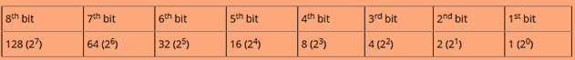
You will be familiar with decimals positions like 10, 100, 1000, 10,000 and so on. Which is nothing but just power to 10. Binary values work in a similar way but instead of base 10, it will use the base to 2. For instance 20 , 21, 22, 23, ….26. The values for the bits ascends from left to right. For this, you will get values like 1,2,4,….64.
See the table below.
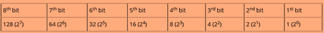
Now since you are familiar with the value of each bit in a byte. The next step is to understand how these numbers are converted to binary like 01101110 and so on. Each digit “1” in a binary number represents a power of two, and each “0” represents zero.

In the table above, you can see that the bits with the value 64, 32, 8, 4 and 2 are turned on and represented as binary 1. So for the binary values in the table 01101110, we add the numbers
64+32+8+4+2 to get the number 110.
Important element for network addressing scheme
IP address
For constructing a network, first, we need to understand how IP address works. An IP address is an Internet protocol. It is primarily responsible for routing packets across a packet switched network. The IP address is made up of 32 binary bits that are divisible to a network portion and host portion. The 32 binary bits are broken into four octets (1 octet = 8 bits). Each octet is converted to decimal and separated by a period (dot).
An IP address consists of two segments.
- 1. Network ID– The network ID identifies the network where the computer resides
- 2. Host ID– The portion that identifies the computer on that network
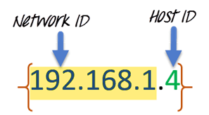
These 32 bits are broken into four octets (1 octet = 8 bits). The value in each octet ranges from 0 to 255 decimal. The right most bit of octet holds a value of 20 and gradually increases till 27 as shown below.
Let’s take another example,
For example, we have an IP address 10.10.16.1, then first the address will be broken down into the following octet.
- 1. .10
- 2. .10
- 3. .16
- 4. .1
The value in each octet ranges from 0 to 255 decimal. Now, if you convert them into a binary form. It will look something like this, 00001010.00001010.00010000.00000001.
IP address classes
IP addresses are classified into different classes:
| Class Categories | Type of communication | |
|---|---|---|
| Class A | 0-127 | For internet communication |
| Class B | 128-191 | For internet communication |
| Class C | 192-223 | For internet communication |
| Class D | 224-239 | Reserved for Multicasting |
| Class E | 240-254 | Reserved for research and experiments |
To communicate over the internet, private ranges of IP addresses are as per below.
| Class Categories | |
|---|---|
| Class A | 10.0.0.0 – 10.255.255.255 |
| Class B | 172.16.0.0 – 172.31.255.255 |
| Class C | 192-223 – 192.168.255.255 |
Subnet and Subnet Mask
For any organization, you might require a small network of several dozen standalone machines. For that, one must require setting up a network with more than 1000 hosts in several buildings. This arrangement can be made by dividing the network into subdivision known as Subnets.
The size of network will affect,
- Network class you apply for
- Network number you receive
- IP addressing scheme you use for your network
Performance can be adversely affected under heavy traffic loads, due to collisions and the resulting retransmissions. For that subnet masking can be a useful strategy. Applying the subnet mask to an IP address, split IP address into two parts extended network address and host address.
Subnet mask helps you to pinpoint where the end points on the subnet are if you are provided within that subnet.
Different class has default subnet masks,
- 1. Class A- 255.0.0.0
- 2. Class B- 255.255.0.0
- 3. Class C- 255.255.255.0
Router Security
Secure your router from unauthorized access, tampering, and eavesdropping. For this use technologies like,
- Branch Threat Defense
- VPN with highly secure connectivity
Branch Threat Defense
- 1. Route guest user traffic: Route guests user traffic directly to the Internet and backhauling corporate traffic to headquarters. This way guest traffic won’t pose a threat to your corporate environment.
- 2. Access to the Public Cloud: Only selected types of traffic can use the local internet path. Various security software like firewall can give you protection against unauthorized network access.
- 3. Full Direct Internet Access: All traffic is routed to the Internet using the local path. It ensures that enterprise-class is protected from enterprise-class threats.
VPN Solution
VPN solution protects various types of WAN design (public, private, wired, wireless, etc.) and the data they carry. Data can be divided into two categories
- 1. Data at rest
- 2. Data at transit
Data is secured through following technologies.
- Cryptography (origin authentication, topology hiding, etc.)
- Following a compliance standard ( HIPAA, PCI DSS, Sarbanes-Oxley) compliance